Building a Secret Cabinet

We’ve recently had the attics of our house converted, and I moved my bedroom up to one of the newly-constructed rooms.

To make the space my own, I did a little light carpentry up there: starting with a necessary reshaping of the doors, then moving on to shelving and eventually… a secret cabinet!

I’d love to tell you about how I built it: but first, a disclaimer! I am a software engineer, and with good reason. Letting me near a soldering iron is ill-advised. Letting me use a table saw is tempting fate.

Letting me teach you anything about how you should use a soldering iron or a table saw is, frankly, asking for trouble.
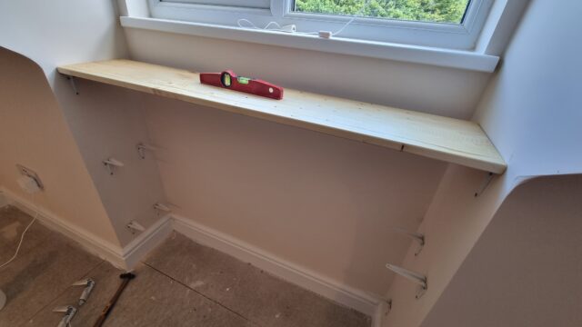
A spirit level on an unfinished shelf, under a window and beneath an uncarpeted floor.
Knowing that I’d been short on shelf space in my old bedroom, I started work on fitting shelves for my new bedroom before the carpet had even arrived.

Building a secret cabinet wasn’t part of my plan, but came about naturally after I got started. I’d bought a stack of pine planks and – making use of Ruth’s table saw – cut them to squarely fit beneath each of the two dormer windows1. While sanding and oiling the wood I realised that I had quite a selection of similarly-sized offcuts and found myself wondering if I could find a use for them.

Dan drinks a 0% alcohol beer in front of three upright planks of wood.
The hardest part of sanding and oiling wood on the hottest day of the year is all the beer breaks you have to take. Such a drag.

I figured I had enough lumber to insert a small cabinet into one of the bookshelves, and that got me thinking… what about if it were a secret cabinet, disguised as books unless you knew where to look. Or to go one step further: what if it had some kind of electronic locking mechanism that could be triggered from somewhere else in the room2.
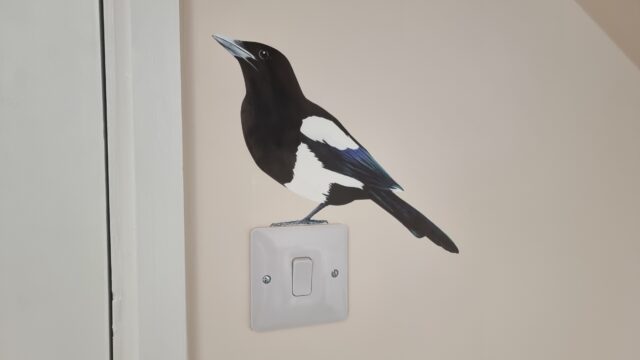
Magpie decal 'perched' on a light switch.
There are other ways in which I’ve made my new room distinctly-“mine” – like the pair of magpies – but probably the secret cabinet is the most-distinctive.

Not wanting to destroy a stack of real books, which is the traditional way to get a collection of book spines for the purpose of decorating a “fake bookshelf” panel3, I looked online and discovered the company that made the fake book spines used at the shop of my former employer. They looked ideal: carefully shaped and painted panels with either an old-school or contemporary look.

Buuut, they don’t seem to be well-equipped for short runs and are doubtless pricey, so I looked elsewhere and found the eBay presence of Beatty Lockey Antiques in Loewstof. They’d acquired a stack of them second-hand from the set of Netflix’s The School for Good and Evil.4

(By the way: at time of writing they’ve still got a few panels left, if you want to make your own…)

I absolutely must sing the praises of Brad at Beatty Lockey Antiques who, after the first delivery of fake book fronts was partially-damaged in transit, was super quick about helping me find the closest-available equivalent (I’d already measured-up based on the one I’d thought I was getting) and sent a replacement.

The cabinet is just a few bits of wood glued together and reinforced with L-shaped corner braces, with a trio of thin strips – made from leftover architrave board – attached using small brass hinges. The fake book fronts are stuck to the strips using double-sided mounting tape left over from installing a bathroom mirror. A simple magnetic clasp holds the door shut when pushed closed5, and the hinges are inclined to “want” the door to stand half-open, which means it only needs a gentle push away from the magnetic catch to swing it open.

Circuit diagram showing a Raspberry Pi Zero W connected to two relays, each connecting 12V DC to a latch solenoid.
The wiring is uncomplicated enough that even I – a self-confessed software engineer – could manage it. Note the separate power supply: those solenoids can draw a full 1 amp in a “surge” that’s enough to give a little Raspberry Pi Zero a Bad Day if you try to power it directly from the computer (there might be some capacitor-based black magic that I don’t understand that could have made this easier, I suppose)!

I mounted a Raspberry Pi Zero W into a rear corner inside the cabinet6, and wired it up via a relay to what was sold to me as a “large push-pull solenoid”, then began experimenting with the position in which I’d need to mount it to allow it to “kick” open the door, against the force of the magnetic clasp7.

This was, amazingly, the hardest part of the whole project! Putting the solenoid too close to the door didn’t work: it couldn’t “push” it from a standing start. Too far away, and the natural give of the door took the strain without pushing it open. Just the right distance, and the latch had picked up enough momentum that its weight “kicked” the door away from the magnet and followed-through to ensure that it kept moving.

A second solenoid, mounted inside the top of the cabinet, slides into the “loop” part of a large bolt fitting, allowing the cabinet to be electronically “locked”.
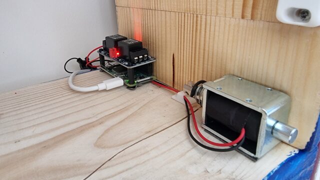
A Raspberry Pi Zero, relay, and solenoid assembly on the bottom outside edge of the inside of the cabinet.
I seriously must’ve spent about an hour getting the position of that little “kicker” in the bottom right just right.

Next up came the software. I started with a very simple Python program8 that would run a webserver and, on particular requests, open the lock solenoid and push with the “kicker” solenoid.

#!/usr/bin/python
#
# a basic sample implementation of a web interface for a secret cabinet
#
# setup:
#   sudo apt install -y python3-flask
#   wget https://github.com/sbcshop/Zero-Relay/blob/master/pizero_2relay.py
#
# running:
#   sudo flask --app web run --host=0.0.0.0 --port 80

from flask import Flask, redirect, url_for
import pizero_2relay as pizero
from time import sleep

# set up pizero_2relay with the two relays attached to this Pi Zero:
r1 = pizero.relay("R1") # The "kicker" relay
r2 = pizero.relay("R2") # The "locking bolt" relay

app = Flask(__name__)

# GET / - nothing here
@app.route("/")
def index():
  return "Nothing to see here."

# GET /relay - show a page with "open" and "lock" links
@app.route("/relay")
def relay():
  return "<html><head><meta name='viewport' content='width=device-width, initial-scale=1'></head><body><ul><li><a href='/relay/open'>Open</a></li><li><a href='/relay/lock'>Lock</a></li></ul>"

# GET /relay/open - open the secret cabinet then return to /relay
# This ought to be a POST request in your implementation, and you probably
# want to add some security e.g. a 
@app.route("/relay/open")
def open():
  # Retract the lock:
  r2.off()
  sleep(0.5)
  # Fire the kicker twice:
  r1.on()
  sleep(0.25)
  r1.off()
  sleep(0.25)
  r1.on()
  sleep(0.25)
  r1.off()
  # Redirect back:
  return redirect(url_for('relay'))

@app.route("/relay/lock")
def lock():
  # Engage the lock:
  r2.on()
  return redirect(url_for('relay'))
Don’t use this code as-is on any kind of open network, obviously. Follow the comments for some tips on what you’ll need to change.

Once I had something I could trigger from a web browser or with curl, I could start experimenting with trigger mechanisms. I had a few ideas (and prototyped a couple of them), including:

  • A mercury tilt switch behind a different book, so you pull it to release the cabinet in the style of a classic movie secret door.
  • A microphone that listens for a specific pattern of knocks on a nearby surface.
I had far too much fun playing about with crappy prototypes.
  • An RFID reader mounted underneath another surface, and a tag on the underside of an ornament: moving the ornament to the “right” place on the surface triggers the cabinet (elsewhere in the room).
  • The current design, shown in the video above, where a code9 is transmitted to the cabinet for verification.

I think I’m happy with what I’ve got going on with it now. And it’s been a good opportunity to improve my carpentry, electronics, and Python.

Footnotes

1 The two dormer windows, wouldn’t you guarantee it, were significantly different widths despite each housing a window of the same width. Such are the quirks of extending a building that the previous occupier had previously half-heartedly tried to extend, I guess.

2 Why yes, I am a big fan of escape rooms. Why do you ask?

3 For one thing, I live with JTA, and I’m confident that he’d somehow be able to hear the silent screams of whatever trashy novels I opted to sacrifice for the good of the project.

4 As a bonus, my 10-year-old is a big fan of the book series that inspired the film (and a more-muted fan of the film itself) and she was ever-so excited at my project using real-life parts of the set of the movie… that she’s asked me to make a similar secret cabinet for her, when we get around to redecorating her room later in the year!

5 If I did it again, I might consider using a low-powered electromagnetic lock to hold the door shut. In this design, I used a permanent magnet and a pair of latch solenoids: one to operate a bolt, the second to “kick” the door open against the pull of the magnet, and… it feels a little clumsier than a magnetic lock might’ve.

6 That double-sided mounting tape really came in handy for this project!

7 Props to vlogger Technology Connections, one of whose excellent videos on the functionality of 1970s pinball tables – maybe this one? – taught me what a latch solenoid was in the first place, last year, which probably saved me from the embarrassment of trying to do this kind of thing with, I don’t know, a stepper motor or something.

8 I’m not a big fan of Python normally, but the people who made my relays had some up with a convenience library for them that was written in it, so I figured it would do.

9 Obviously the code isn’t A-B; I changed it temporarily for the video.

× × × × ×

You Can’t Do It Alone!

Hot on the heels of the Oxford Steganography Series, a series of “hidden in plain sight”-themed geocaches I placed earlier this year, I’ve recently placed another geocache – GC591VV – and I think that – conceptually – it might be completely unique.

Spoiler warning: this article contains minor spoilers about Oxford-based geocache GC591VV – “You Can’t Do It Alone”. You won’t find any shortcuts by reading this page, but you might ruin part of the surprise.

Geocache GC591VV, ready to hide

The cache’s name is the first clue that there’s something unusual about it, and this theme continues in its description, where it insists that this is a cache that is impossible to find by yourself. Experienced ‘cachers may have come across geocaches that benefit from a second pair of hands: usually to help “bunk you up” to a high spot. Some really clever caches use your “buddy” to press a battery-powered radio doorbell while you “listen” for the cache’s hiding place nearby, or use your friend to stop up the holes in a pipe as you pour water into it (in order to raise a floating cache to the surface). But every single one of these has a “workaround” – a way in which you can do it by yourself, if you’re imaginative enough. I wanted to make a cache that genuinely required two people.

Dan reprogrammes Box One in a forest
Creating this geocache took months of planning, scouting, construction, and – on one unfortunate occasion – standing around in the rain, deep in a forest, with a C debugger.

The cache description page repeatedly insists that to solve the cache, you need you and a friend to simultaneously visit two different waypoints. When you and your friend get there, you discover why: at each, I’ve hidden a small electronic device, specially-built for this purpose (and instructions on how to use it). The two devices are a synchronised pair, and each shows on its screen a pair of numbers. To find the location of the cache itself, you need to add the first number on Box One’s screen to the first number on Box Two’s screen… and the second number on Box One’s screen to the second number on Box Two’s screen. But… the numbers change every 15 minutes: and because both boxes are hidden on opposite sides of Oxford, there’s no way to get from one to the other within the narrow window. Truly: you can’t do it alone!

Box One and Box Two stess test
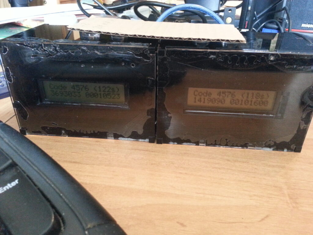
The numbers shown on the screens in this photo, taken during their month-long “stress test”, are fake (they point to N 51° 12.123, W 001° 12.123: that’s not where the cache is).

Once the two cachers have each other’s numbers, they can head on to the final coordinates: the actual location of the cache: they can race there, if they like (it’s close-to equidistant from the two points) – though if they’re feeling that competitive, they’ll probably want to agree on some key exchange mechanism by which they can swap numbers without giving the person to speak first a disadvantage: I’ll leave that mathematical exercise for somebody else to solve, though! In any case, I’ve been sure to put two “first to find” prizes into the cache: one for each of the people who worked together to find it.

Visual schematic for You Can't Do It Alone boxes
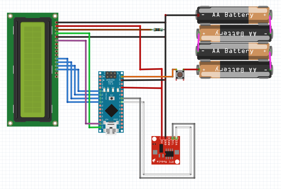
Each box is operated by a pile of dirt-cheap Chinese-made components, inexpertly soldered together by me.

How does this magic work? Well, it’s reasonably simple, so long as you’re familiar with the conceptual workings of time-based two-factor tokens and the predictability of computer random number generators. I’m offering the source code and support in construction to anybody who successfully finds the cache, in order to try to inspire a new generation of digital caches in Oxfordshire (and further afield!). But the essence of it is an ATmega328 chip acting like an Arduino Nano, hooked up to a clock chip (powered by a long-life lithium “watch battery”) that keeps it in sync with its partner, and – while a switch is pushed – fully-powered by a stack of AA batteries (which provide enough power to do the maths and light up the screen).

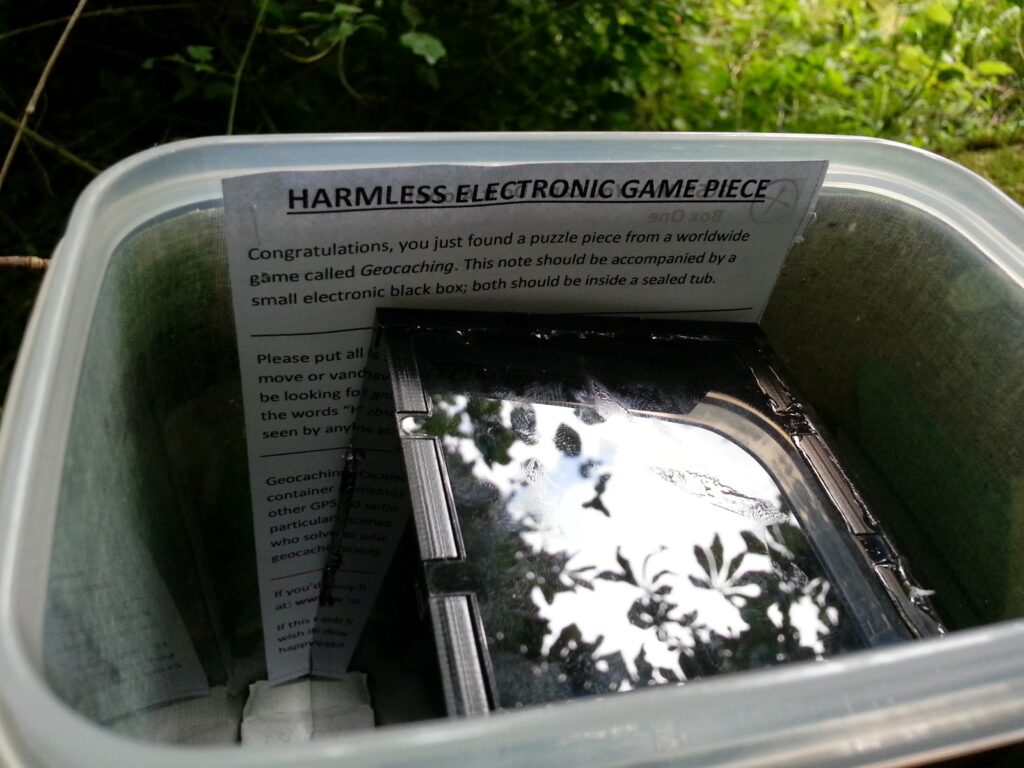
Harmless Electronic Game Piece, written above Box One, in situ
Given how alarmed people sometimes get when they find sealed black boxes with digital screens, slowly counting down, I decided to include a reassuring note with each box.

The whole package is sealed up inside a custom-built acrylic box (courtesy of RazorLAB, whom I discovered after Rory did a craft project using them), and I’m hoping that they’ll live at least a year before I need to get out there and replace the AA batteries.

This cache represents a huge leap in complexity over anything I’ve placed before, and – I think! – might be completely unique in design, worldwide. I’m really looking forward to seeing what the community make of it! Want to go find it yourself? Start here!

Update (2018): This cache has now been retired. If you’re interested, you can read the source code here.

× × × × ×

How To Repair A Nintendo GameCube

For the last few months, Claire and my GameCube has been broken. It broke at one point, which I attributed to the drive motor being jammed up with dust and hair and crap, so I opened the lid and wiggled a knife-blade around inside it for awhile, which seemed to fix it… but a couple of weeks later, it was dead again. I decided to have another look into this, yesterday, and a little bit of research online revealed that the problem was probably that the strength of the laser had degraded, rendering it unable to read any discs. This is, apparently, one of the most common causes of death for the GameCube (and I’ve seen a good number of ‘cubes go on eBay which would appear to have exactly this problem). Thankfully, there’s a really well-written guide on lens calibration for the gamecube, which helped a lot. However, the thing that’s lacking online is a photographic guide: so, as part of this ‘blog entry, I’ve written one.

Usual disclaimer: following this guide will void your warranty. Plus, if you do it the way I did it, you risk electrocution, exposure to laser radiation, and worse yet, you may break your GameCube beyond repair.

I recommend that you read the guide to lens calibration for the gamecube – it’s far more in-depth than this blog entry. However, this blog entry has prettier pictures.

Symptoms

  • GameCube fails to load games – it claims that the disc is missing or unreadable, and will only load up as far as the “configuration cube” screen with the funky ambient noises.
  • Open the lid and detach the clips under the lid to release the circular plastic Nintendo-branded thing that sits on top of the lid: this will allow you to watch the disc spinning while the ‘Cube is running, even with the lid closed. Try again – the disc will start to spin (so, it’s not a broken drive motor) but then stop (when the system finds it can’t read the disc).

Problem

The power output of the laser which is used to read the surface of the disc has reduced with age. This is a common problem in GameCubes, apparently, between two and five years old. It can be repaired by a Nintendo engineer, but the price is prohibitive (you might as well buy a working second-hand one). However, we can fix it ourselves. [if you can’t see the rest of this article, read it here]

Tools

I didn’t have all the tools to hand that the author of the guide I followed had, but I made do. Here are my tools:

 Screwdriver and ball-point pen
  1. Screwdriver – this is a standard “size 0” (small, but not really small) Phillips-head screwdriver. This particular one cost me 45p from my local hardware store.
  2. Ball-point pen – mine was a WHSmiths-branded one with blue ink.

Method

First step is to prepare the tools as you’ll need them. The four main case screws that prevent you from taking a GameCube apart are a strange custom design deeply recessed within deep holes on the underside of the device. You can apparently buy a specialist tool for manipulating these screws, but I couldn’t be bothered, so I made one: remove the ink tube and nib from the pen, so you’re left with a long plastic tube. Then, using a hot flame (I used a gas ring) melt/ignite the end of the tube you’d normally write with (where the nib was, before you removed it). It will probably catch fire, but just blow it out while trying not to breathe in too much of the toxic black smoke you’re producing. It needs to be molten enough to be malleable. Then, once it’s hot, put it down into one of the four deep holes on the underside of your upside-down GameCube.

 Upside-down GameCube with holes highlighted

Push it down firmly but evenly so that it points directly up, and hold it there for a minute or so while it begins to take shape. What you’re doing is moulding the shape of the screw head into the molten plastic of the pen, so that when the plastic sets you will have a tool that exactly fits them. Of course, if then pen snaps, you’ve buggered any chance you had of ever getting into your GameCube, so be careful! Once it’s standing upright by itself, leave it for four or five minutes to finish cooling. Now’s a good opportunity to read the rest of this guide, if you haven’t already.

 The strange-headed screws that you need to remove

You should now be able to use your new tool to unscrew the four screws that hold your GameCube together. That’s the hard bit over with. Flip your GameCube the right way up again, put your hands on it’s sides, and pull upwards to remove the cover. If there isn’t one already, put a GameCube disc onto the spindle. This will serve two purposes: it will allow you to test the GameCube without reassembling it, later, but more importantly it will help to protect the laser lens from damage when you turn the drive mechanism upside-down, later. Next you need to remove the front and rear panels. These are attached by small plastic clips in the corners of the cube, as shown below.

 Howo to remove the front panel from a GameCube

Be careful not to detach the cables that connect the front panel to the rest of the GameCube, as these ribbon cables are very difficult to re-attach without damaging them! Now you’re ready to start removing the chassis screws (which are holding the fan in place and preventing you from getting at the underside of the disc drive. There are 14 screws to remove, in the areas shown below, but 3 of these are concealed underneath the fan and the 2 holding the fan in place will need to be removed to reveal them. Why did Nintendo see fit to use 14 screws where 6 would have done is beyond me.

 The 14 screws

By now you should have something that looks a lot like this:

 The 14 screws

A GameCube with the top, sides, and fan laid bare, and the screws removed from the main chassis. Now’d be a good time to have a closer look at what goes on when your ‘Cube turns on. This is optional, but I think it’s interesting. If you look near the back of the GameCube, on the right-hand side, you’ll see two plastic forks. This is the switch that detects whether or not the lid is closed (as a safety precaution, the disc will not spin and the laser will not turn on if the lid is opened).

 The switch that makes the lid work

Danger: laser radiation – do not do this! Connect the GameCube’s power (it connects to the back of the fan module) and output (where it normally is, albeit without the faceplace), to test it. Hold the “lid switch” (above) backwards to tell the GameCube that the lid is closed and press the power switch (it’s on the fan module). You should see the following happen:
  1. The power LED will turn on.
  2. The disc will start to spin.
  3. The laser, under the disc, will turn on. You should be able to see it shining through the disc. Now stop looking at it; you’re irradiating your eyes.
  4. The laser will move back and forth to try to “read” the disc.
  5. At this point, the laser will probably turn off and the disc will stop spinning – this is because the GameCube you’re using is broken. If it was working, the game would load. You can use this test later on to see if you’ve successfully fixed the device without having to re-assemble the entire thing!
  6. Don’t leave it running too long, because by this point the fan will be in the wrong place to help cool the unit.

Next, you need to remove the four long screws behind the ports (above the memory card slots).

 Four earthing screws need to be removed


This will also release two strange bits of metal which are held in place by these screws. I don’t know what they do, but I’m sure they’re probably important, so make sure you put them back after you’re done! Right; time to detach the disc drive. Lift the entire upper part of the system up and away from the base: there’ll be a little resistance as a plug becomes detached, but if you find you’re having to pull hard, you’ve probably left a screw in somewhere. The whole metal plate with the drive on top will come away in one piece. This is the bit we’ll be working with. Flip it over. Now, you’ve got to remove six small screws, highlighted in red on the photo below. I’ve also highlighted (in blue) the connector that links the drive to the bottom half of the console.

 Underneath the upper chassis

Removing the screws allows you to detach the metal plate and gain access to the circuitboard underneath. This is what we’re looking for. Again, I’ve highlighted the connector port in blue to help you navigate.

 Circuitboard

What you need to do is to turn the screw (highlighted in red) about 3 or 4 degrees anti-clockwise. This will increase the power given to the laser and fix your problem. If you turn it too much, your laser will overheat and burn out. If you turn it too little, the problem won’t be fixed. I recommend that you turn it a little at a time to find how short a distance you can turn it (anti-clockwise) to have the console begin to work again (i.e. so it “barely” works)… then turn it an extra 2 degrees or so to be sure. Be gentle!!! When you’ve made the adjustments you want to, re-assemble the thing so far as you need to to test it. You don’t need to put any screws in or even put the fan or panels back on – just hook it up to the TV and try not to look directly at the laser lens. If it still doesn’t work, go back and turn the screw a little more anti-clockwise (to boost the power some more). Hope that helps you get your GameCube back up-and-running again: it did mine! Feedback is welcome, but if you need more information I still highly recommend Lens Calibration For The Nintendo GameCube, which also has pointers on some of the other things that could be wrong (if this fix fails), what tools you need to do it without melting pens, and tips from somebody more-experienced on how far to turn the circuitboard screw. Good luck!